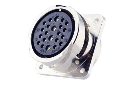
Amerline offers COTS connectors that are interchangeable with MIL-SPEC connectors. Rigorously tested for durability, environmental resistance, and reliability, these connectors meet essential standards, making them ideal for diverse applications. By ensuring compatibility with MIL-SPEC components, Amerline streamlines operations while reducing procurement costs.
What Is a Contact Arrangement?
Key Takeaways
- A contact arrangement is the number, size, spacing, and physical layout of the pins and sockets inside a connector's insert that carry current across a connection.
- It's built from four core parameters — number of contacts, contact size, contact spacing (pitch), and physical layout — plus contact shape and type (pin or socket).
- Getting the arrangement right the first time avoids mismatched wire gauge, wasted shell space, or a costly redesign later on.
- Amerline's AEC connectors, including the 5015, 26482, 95234 Reverse Bayonet, and 22992 series, use the same contact arrangements as their MIL-SPEC counterparts and stay interchangeable and intermateable with them.
- When a standard arrangement doesn't fit an application, Amerline's engineering team can design a connector around a custom contact arrangement built to spec.
A contact arrangement is the configuration of contacts inside a connector's insert: the number, size, spacing, and physical layout of the pins and sockets that carry current from one side of a connection to the other. It determines if a connector, be it a MIL-SPEC connector or a commercial equivalent, can support a straightforward low-density signal run or a high-density, high-current configuration. Getting it right the first time avoids mismatched wire gauge, wasted shell space, or a redesign down the line.
What Parameters Define a Contact Arrangement?
Number of Contacts
The number of contacts is the total contact, or circuit, count the insert holds. Every wire that needs to pass through the connector requires its own dedicated contact position. This can range from a single power contact in a simple two-wire connection to 100+ contacts in dense multi-circuit configurations.
Contact Size
Contact size is an assigned number — such as #20, #16, #12, #8, #4, or #0 — that correlates to AWG wire gauge and sets how much current a given contact can carry. The number refers to the diameter of the contact's engaging end: smaller numbers denote larger, higher-current contacts, while larger numbers denote smaller, lower-current contacts. Matching contact size to the wire gauge on each circuit is essential, as an undersized contact on a high-current circuit is a safety and performance risk.
Contact Spacing (Pitch)
Contact spacing, or pitch, is the center-to-center distance between adjacent contacts within the insert. It affects how densely an insert can be packed and how much mating force is required to connect the two halves.
At the same time, proper spacing between contacts helps balance out heat generation and boost efficiency. Contacts placed too close together can concentrate heat within the insert and reduce current-carrying capabilities.
Physical Layout
Physical layout is the geometric pattern the contacts follow across the insert face. They're typically arranged in concentric rings or grids, depending on the connector family and shell size. Layout drives polarization, meaning it verifies the connector can only be mated one correct way. It also influences how efficiently a given shell size can be used. Two arrangements with the same contact count and sizes can still differ in layout, which is why insert arrangement drawings are the reference point engineers use when specifying a connector.
Beyond these four parameters, it's worth noting that contacts vary by shape and type, such as pin versus socket, for instance. A connector's pin half and socket half need matching arrangements so every contact finds its corresponding element and completes the electrical path on mating.
Why Does Contact Arrangement Matter for Connector Selection?
Choosing the correct arrangement ensures the insert accommodates both the circuit count and the wire sizes the application requires. Additionally, it determines if that insert can handle a high-density cable bundle, a high-current power run, or some combination of both within the same shell.
The Difference Between Contact Arrangement and Insert Arrangement
"Contact arrangement" and "insert arrangement" describe the same concept and are used interchangeably across MIL-SPEC standards, manufacturer catalogs, and engineering documentation. The insert is the dielectric (insulating) molded component inside the connector shell that physically holds and positions the contacts. The contact arrangement specifies which contacts go where inside it.
Inputs You Need Before Choosing a Contact Arrangement
Number of Circuits
Start by counting how many conductors, or wires, need to pass through the connector. This is the baseline circuit count the insert has to support, and it's the first filter that narrows down which arrangements and shell sizes are in play. Underestimating this number early on is a common reason designs have to be revisited later, so it's worth accounting for any circuits that are planned but not yet active.
Wire Gauge per Circuit
Once circuit count is set, identify the AWG size of each wire. Wire gauge maps to the contact size required for that circuit; a heavier-gauge wire needs a larger contact to terminate properly, while a lighter-gauge wire can use a smaller one. Since arrangements can mix contact sizes within a single insert, this step often produces a mixed list of contact sizes rather than a uniform size across the whole connector.
Current and Voltage Requirements
Every contact size carries a current rating, so the current and voltage each circuit will see needs to be matched against that rating. Size the contact to the highest current-carrying circuit it will handle, with enough margin to account for real-world conditions.
Voltage requirements also factor into insert material and spacing decisions. Higher voltages generally call for greater separation between contacts to maintain adequate insulation resistance.
Available Package Space
Connector shell size is constrained by the physical envelope of the application where the connector has to fit. Larger contact arrangements, whether because of higher contact counts or larger contact sizes, require larger shells, so available space can be the limiting factor even when the electrical requirements would call for something bigger. Confirming package space early can rule out otherwise ideal arrangements before any other selection criteria come into play.
Connector Family / MIL Standard
Arrangement options vary by connector family and governing specification. MIL-DTL-5015, MIL-DTL-26482, and MIL-DTL-22992 each define their own set of approved insert arrangements, shell sizes, and contact size ranges. The right family comes down to the application: MIL-DTL-5015 and its AEC commercial equivalents cover a broad range of general power and signal uses, while other families are built around more specialized density or power requirements. Confirming which standard governs the application keeps the rest of the selection process anchored to the correct set of approved arrangements.
Contact Arrangements for Amerline's AEC Connectors
Amerline's AEC line covers commercial equivalents across the major MIL-SPEC connector families — AEC 5015, AEC 26482, AEC 95234 Reverse Bayonet, and AEC 22992 — which means their contact arrangements carry over directly and stay interchangeable and intermateable with the corresponding MS connector families. That means the arrangement decisions covered above apply the same way whether you're working from a military print or specifying an Amerline commercial equivalent.
Across the AEC portfolio, arrangement options span from compact, high-density configurations to larger, high-current arrangements built for heavy-duty power distribution. Inserts are tooled for each shell size and contact arrangement, and resilient insert materials support environmental sealing performance.
Not every application fits a standard arrangement. When an off-the-shelf insert arrangement can't accommodate a project's circuit count, mix of contact sizes, or spacing requirements, Amerline's engineers can design a connector around a unique contact arrangement for that application. Reach out to talk through your specific requirements.
Frequently Asked Questions About Contact Arrangements
What is contact arrangement in a connector?
Contact arrangement is the configuration of contacts within a connector, defined by the number, gauge, spacing, and layout of contacts held within the insert. Selection is determined by the current and voltage requirements of the application and the available space within the connector package.
What is the difference between contact arrangement and insert arrangement?
The insert is the molded dielectric component inside the connector shell that holds contacts in position. Contact arrangement, or insert arrangement, defines how many contacts are present, their sizes, and their physical layout within that insert. Both terms appear across MIL-spec standards and manufacturer catalogs for the same concept.
What are the selection criteria for choosing a contact arrangement?
The primary inputs are: the number of circuits required, the wire gauge (AWG) for each circuit, the current and voltage rating needed per circuit, and the available package space for the connector shell. You select the arrangement that meets or exceeds all of these requirements; an arrangement with extra unused positions is acceptable if an exact match isn't available.
Are Amerline AEC connectors compatible with MIL-SPEC connector families?
Yes. Amerline AEC connectors are commercial equivalents interchangeable with corresponding MIL-SPEC connector families, including MIL-DTL-5015, MIL-DTL-26482, MIL-DTL-22992, and AS95234 (VG95234). AEC connectors use the same insert arrangements and mate with their military-standard counterparts.
Can I get a custom contact arrangement from Amerline?
Yes. Amerline offers custom design services for applications requiring non-standard contact arrangements, including a unique combination of contact sizes, counts, and layouts within a given shell size. Contact Amerline's engineering team to discuss custom configuration options for your application.